Interior of Hydraulic Power Station, North Dock, Newport 1914
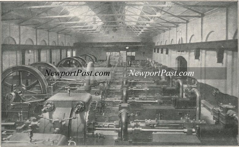 Photo reference number: 1307
From "The Alexandra Docks, Newport" published 1914:
"As the Hydraulic Power Station, situated at the north end of the North Dock, is the present centre from which is distributed the pressure water operating the whole of the hydraulic plant on the Docks, it may be of some interest to describe in general terms the principal features of the installation.
"The Station consists of a brick building, including Engine House, Boiler House, Pump House, and Economiser House. At the south end of the building is the chimney stack about 140 feet high, and at that end of the building are situated also three storage and controlling accumulators.
"In the Engine House are installed four sets of horizontal triple-expansion surface-condensing pumping engines, arranged transversely. Three of these are capable of developing 600 Indicated Horse Power each, and the diameters of the cylinders are, H.P. 24", I.P. 36", and L.P. 56", the stroke being 36", and the piston speed 240 feet per minute. The quantity of water each of these engines is capable of delivering at a pressure of 750 lbs. per sq. inch is about 920 gallons per minute. These three engines, which were installed in 1903, are fitted with Corliss valves.
"In 1907, the fourth set, of considerably greater capacity, was put down, capable of developing 820 I.H.P. The diameters of the cylinders of this engine are : H.P. 28˝", I.P. 43", and L.P. 66", the stroke and piston speed per minute being the same as in the other sets. This engine is fitted with Van de Stegen piston drop valves, and is capable of delivering 1,224 gallons of water per minute against a pressure of 750 lbs. per square inch.
"There are six single-acting pressure pumps to each set of engines, with barrels of cast steel, lined with gun metal to prevent any corrosion from the action of the water. These pumps are connected to the piston-head by means of two tail rods, working through stuffing-boxes in the back covers of the cylinders.
"The pump rams, which are 6 1/8" in diameter in the smaller sets, and 7 1/16" in
diameter in the larger set, are connected to the tail rods by means of a crosshead, and slipper working on a slide tie bar fixed longitudinally between the pump barrels. Water is delivered by one pump whilst the other is drawing its supply.
"The supply of water for hydraulic pumping is conveyed by means of a culvert from the dock into a well beneath the Station, and is then delivered by a quadruple double-acting hydraulic pump into the overhead supply tanks placed in a building immediately adjacent to the Engine Room. It is drawn thence by the pumps and delivered into the pressure mains, and after doing its work is returned to the dock. In the case of the larger set of engines, the independent supply pump is not required, as the engine maintains its own supply to the tank for the hydraulic pumps. The condensers and circulating pumps are fixed in recesses in the engine foundations.
"Steam is supplied to the engines at a pressure of 185 lbs. per square inch, and is generated in a range of seven Lancashire boilers, arranged to blow off at a pressure of 200 lbs. Three of the boilers are 28 feet long by 7 feet in diameter; two are 28 feet long by 8' 3" in diameter; and the last two are 28 feet long by 7' 6" in diameter. They are all provided with superheaters, and five of them are fitted with Mechanical Stokers. The boilers are connected to an economiser of six batteries of 64 tubes each, which raises the temperature of the feed water from about 40 to 300 degrees Fahr.
"The make-up water for feeding the boilers is obtained partly from the Town supply and partly from the Company's own fresh water supply. The condensed steam from the engines is delivered into the hotwell tank, and is thence passed through the water softening and de-greasing plant before it is again passed through the economisers to the boilers.
"With regard to the three controlling accumulators each of these consists of a vertical cylinder in which is a ram of 20" in diameter. The top of the ram is connected by means of a large crosshead to the cylindrical casing which surrounds the cylinder, the casings being weighted to secure the desired pressure. The object of these accumulators is to store a reserve of power and to equalize pressure during sudden variations of the load. It is obvious that the pressure in the mains would otherwise vary considerably owing to the fluctuating demands for water by the hydraulic appliances. One of the three accumulators is arranged so that in the last ten feet of its lift it controls the engines by automatically starting and stopping them. In addition to these accumulators there are others at various points round the Docks for storing and equalizing pressure. The pressure water is conveyed to the various hydraulic appliances about the Docks by means of cast-iron pipes of diameters varying from 3" to 8", laid in the ground. The 8" are used solely as feeder-mains to supply water to the other sizes to which the different machinery is connected.
"The maximum speed of the engines is 40 revolutions per minute, but the average speed is considerably less than this. The total number of gallons pumped is steadily rising, and is now in the neighbourhood of 500,000,000 gallons per annum.
"By means of the power derived from this single Station, the whole of the Company's coal hoists and hydraulic cranes is at present worked. Every ton of coal shipped, every ton of general cargo stowed or discharged, has been operated by the power derived from that source, the total for one year now aggregating over seven million tons, a record for a single Station.
"In addition to the coal shipping appliances and cranes, the power derived from this installation also operates the Lock Gates of the North Lock, South Lock, and New Lock; the Rolling Bridge over the South Lock, and the Swing Bridge over the Junction between the North and the South Alexandra Docks, as well as a large number of Capstans."